I have finally spared the time to write about the toroCam, and there has been an unbelievable amount of progress since the last update. Not only do we now have an updated Android app, but also an IPhone app, which only has a few things left to sort out. On my side – the hardware, we have developed several revisions of the mini, which the bulk of the focus has been on, making it as small as possible, incorporating the Bluetooth module directly soldered to the board, and using a micro USB connector for the rechargeable battery. Since then, I have totally redesigned the pro board layout to use almost entirely surface mount components, with the mini as a basis. This has enabled me to get its size down to something that is much easier to fit into your pocket. I am now awaiting some 3D printed case prototypes for the Pro board, which should be here within the next week or so.
The toroCam Mini
Since my last update this is where much of the work was focused, I started from scratch, incorporating only the parts most essential to the toroCam. Besides the IC and Bluetooth module, this included a single jack for the camera, an IR LED, and a micro USB port for power. I soon followed this up with another revision, which included several more additions, such as support for the much smaller surface mount Bluetooth module, a 2032 coin cell holder, and the ‘Smart Power’ system, similar to that on the toroCam Pro. Finally, I created a version which had support for a rechargeable battery. I chose to go down this route, as the extra component cost was minimal, yet it allowed me to totally disregard accessibility to the battery. On the latest version, the battery can either be a rechargeable coin cell, or any other 3.7v lion battery, which can be easily attached via two 0.1″ pitch connectors. This is the stage which the toroCam Mini is currently at, it is also shaped to fit into a small ABS enclosure.
toroCam Pro
PCB Design
After spending much of my time focusing on the design of the toroCam Mini, I then decided to turn my attention back to the Pro. When I went back to the Pro, I realized I had really left its design behind, so I decided that my best option would be to completely start over on the pro. I took the toroCam Mini board design as a basis, before adding in all of the parts that are unique too the Pro. I also tried to use all surface mount components, this helps maximize the about of work that could be automated, in order to help reduce production time and cost. This also resulted in a toroCam Pro model which was over 50% smaller than the previous version.
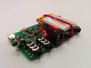
this image shows the a rear view of the toroCam Pro, with the Bluetooth module visible
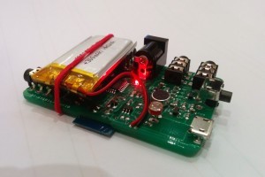
this image shows the a front view of the toroCam Pro, with the various input and output ports visible
Case
Since creating the much smaller toroCam Pro I have been scouring the internet for different cases which I could adapt the design to fit into. However, there was nothing suitable that I could find. With this in mind I decided to create my own case. I started by drawing out all of the internal dimensions onto a piece of paper, making sure everything was correct to the nearest 0.1mm. This then enablled me to create a 3D model of the case in AutoCAD. I then designed some clips, as well as a series of Icons to help identify the functions of each port, which were inset into the outside of the case design in AutoCAD.
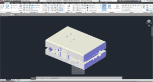
This image shows the toroCam Pro case, being designed within AutoCAD, the case has a detachable hot-shoe mount on the bottom which is not visible.
It seems to be a perfect fit, and makes the toroCam much more usable, as it is now in a much more convenient package.
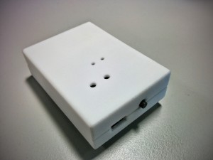
This image shows the toroCam Pro in its case.
toroCam Website
I have also made some rather significant changes to the toroCam Website since my last update. This includes a new color scheme, and a newly optimized mobile format. I hope to make a few more changes in the near future as well, following the updated circuit boards.